The Eurorack system doesn't have much left in common with the Eurocard (and VME) standards that shared the same physical racking factor. In particular the modules no longer need to plug directly into connectors on a circuit board backplane, which is a good thing. The idea of carry-on modular systems would never have evolved if modern Euro systems were stuck with the 160mm-length Eurocard format found in the the Elektor Formant!)
One thing that has remained in the Eurorack standard and is *not* a good thing is the idea of circuit board backplane. What worked well for digital signal buses and computer circuit cards is not so hot for analogue modules that depend on a clean supply for best operation. Why? Synth modules depend on analogue voltages to send pitch control data-and a semitone is just 83.3millivolts in the 1V/octave standard. If a synth module uses the supply rails to power its tuning pots or internal current references and there are fluctuations on the power rails then that creates a problem, most commonly manifesting in the dreaded "module crosstalk".
There are two places this can originate. One is the power supply itself. Every power supply has a "load regulation" spec, which describes how much fluctiuating current draw on the supply output will change its output voltage.
The other place is the distribution system. In a lot of electronic design the resistance of circuit board traces can be disregarded, but they still have a finite resistance. This matters when a sudden change in supply current (such as an LED turning on with 20mA current) creates a voltage drop across the finite resistance of a busboard line thanks to Ohm's law. How much is this "common mode resistance" which can affect other modules plugged in nearby? Let my new 30 year old toy tell a story...
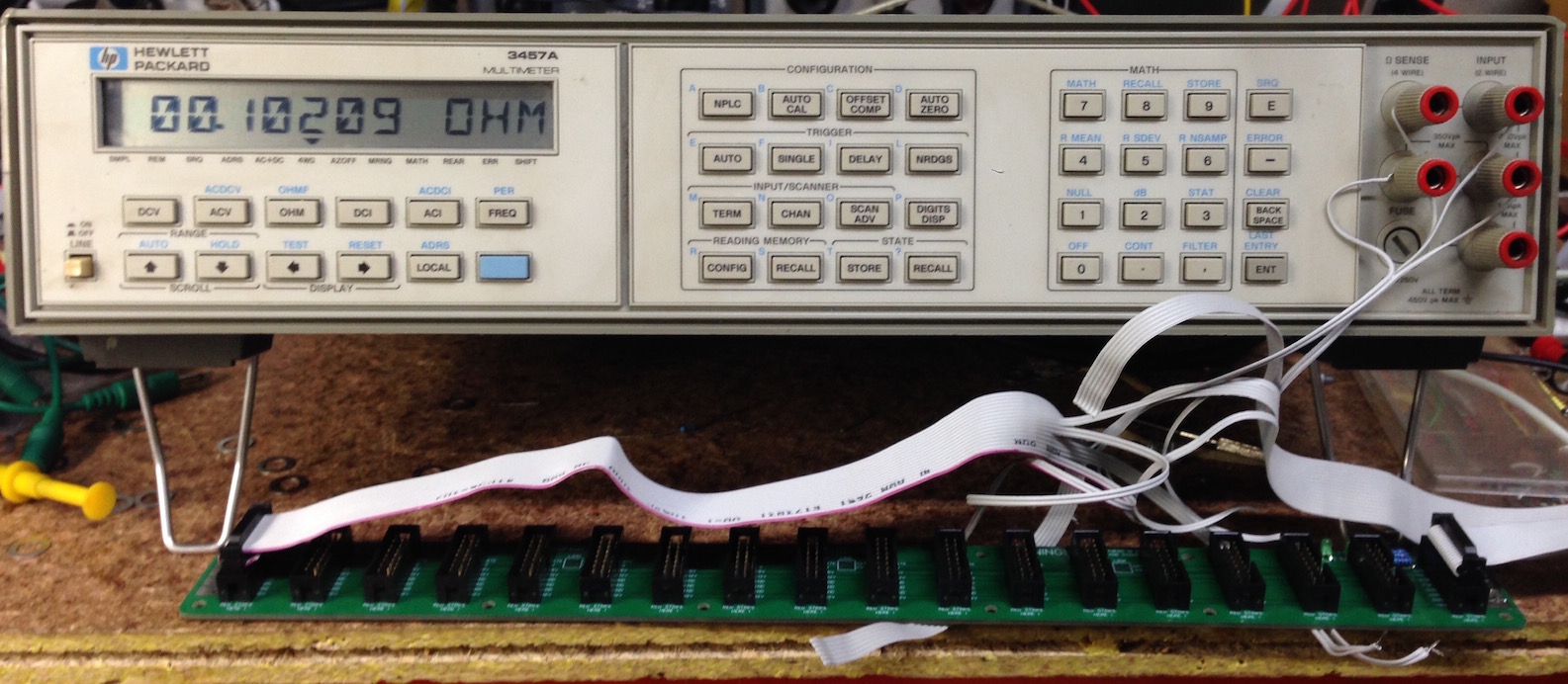
The busboard with its +12V rail under test is one where I had trouble with module crosstalk, and the further from the power supply connection the modules were plugged in, the worse the problem was. The reading on the screen (0.1 ohm) offers a clue. Using 4-wire measurement means that the measuring current and the actual metering wires are kept separate until they enter and leave the busboard itself - power ribbons, and even the header connectors are kept out of the loop so just the resistance of the circuit traces and solder are measured.
So with our 20 milliamp LED blinking blinking furiously at the opposite end of the busboard to the power inlet, the 12 volt rail will be fluctuating by 2 milivolts for any module plugged in right next to it. For a lot of CV-controlled modules that will be audible as a slight warble. Add multiple modules with LEDs or other sources of current fluctuations (such as certain oscillators) and soon you'll have a real problem.
So what's the answer? If you look at other modular formats this is not so much of an issue, and it's no coincidence that Euro is about the only format that generally forces power lines to go through long thin PCB traces to supply a system's worth of modules. So, it doesn't have to be that way. Check this out for starters..and stay tuned to this site!
17/2/27